D-fiber etching can be used for two purposes:
1)To remove the cladding and expose the core
2)To remove part of the core itself
Both of these processes are used here at BYU, the first for making surface relief fiber Bragg gratings and the second for core replacement technologies.
The goal is to perform these processes on a contiguous piece of optical fiber without destroying the
integrity of the fiber. For core removal, it is also desirable to provide a gradual transition into the core.
D-Fiber Doping Profile
The optical fiber has the following materials:
Undoped outer cladding
Fluorine doped inner cladding
Germania doped core
Undoped region near the center of the core that is a result of the manufacturing process
Selective Chemical Etching
In addition to changing the index of refraction, the doping also changes the rate at which the material etches in hydrofluoric (HF) acid.
Doping
Index of refraction
Relative etch rate
Undoped
1.444
1.0
Fluorine doped
1.441
~1.4
Germania doped
1.476
~11x
Here is a little simulation of the core being etched from a fiber.
The red part represents the germania-doped core.
The outer blue part is the fluorine-doped cladding.
The blue in the center is a region of undoped silica in the core.
Press the play button to see the animation.
Since the core etches much more quickly than the cladding, we can remove or partially remove it,
while maintaining the main shape of the fiber.
A groove is created in the core region.
Cut approximately one meter of D-fiber from the spool. This should be long enough to allow maneuverability of the fiber holder in the setup without putting tension on the fiber.
Put on appropriate gloves for handling Dichloromethane.
For the middle of the fiber, locate the middle of the fiber and hold it in a loop. As long as the jacket is still on the fiber, it can go into a fairly tight loop. If a section without jacket is bent into a loop tight enough to go into the vial, it will most likely break.
For the ends, simply dip a little more than 2cm of the fiber into the dichloromethane.
Lower the section of fiber to be stripped into the vial of dichloromethane and let sit for a few seconds.
Pull the fiber out of the vial and pull your fingers along the dipped section of fiber. The jacket should crumble off in your fingers. Stop pulling when the stripped section is long enough. Two centimeters is usually a good length for an etch.
If the jacket did not come off, try the process again.
Turn the fiber so that the flat side is up. As you twist the fiber in your fingers, the point where the light reflects off most brightly is the flat side.
Slide the cleaver blade across the flat side of the fiber.
Gently bend the fiber by pushing on the end until it breaks at the point it was cleaved.
Examine the cleave using a 40X objective. If the fiber is properly cleaved you will see a 'D' when viewed through the objective. If you do not see clear 'D', recleave it.
NOTE: The only way to get valid max throughput measurements is to have "perfect cleaves".
Place the fiber over the holder so that the etched region is in the center.
Replace one of the top magnets.
Let the other end of the fiber hang down in a natural way. It will naturally curve so that the flat side is up.
Pull the fiber tight and replace the other magnet.
Remove the first magnet and repeat for that side. It may take several attempts to get the fiber straight. Test by sliding the magnets together. The fiber should bend in a curve that goes straight down as shown.
The fiber must be able to make a loop deep enough to allow the 2cm stripped region to be submersed in the HF.
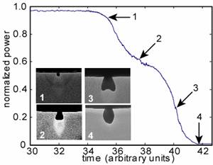
The power transmitted through the fiber is monitored as the fiber is being etched. The power transmitted is related to the amount of core removed. Power monitoring enables tighter control over the amount of core removed.
Place a metal pan beneath a fume hood. This is for safety purposes as you will be using HF.
Fill a water container with deionized water and place it in the metal pan.
Place the fiber holder with the fiber on top of the water container.
Focus the laser into the fiber.
Record the max power, temperature, and any other desired values .
Decide how deep into the core you want to etch. The deeper you etch, the greater the loss in power as you etch. We have had best results with a 7-10dB cut.
Calculate the power at which you must remove the fiber from the acid. This can be calculate from PF=P0*10(-L/10), where PF=Final power, P0=Initial max power, L=desired loss in dB.
Put on necessary safety equipment for working with hydrofluoric acid: apron, splash goggles, face shield, nitrile gloves.
Place a container of 25% HF into the metal pan and remove the lid.
Place the fiber holder on the HF container and move the magnets until 2cm of fiber are in the etchant. Start a timer. (Do not breathe the fumes.)
Monitor the etch by watching the power and timer. Etching time will vary based on the acid and the desired depth. It normally takes about 30-40 min. to reach the core.
When the output power begins to dip significantly (approximately a .3-.5 dB cut from P0, or point 1 in the figure above), the core has been breached. Remove the fiber from the 25% HF and place it immediately into the DI water.
Replace the lid on the 25% HF and remove it from the metal pan.
Slide the magnets on the fiber holder outward to straighten out the fiber.
For surface relief fiber Bragg gratings, this is all the etching that needs to be done in the HF.
For core removal, place a container of 5% HF into the metal pan and remove the lid. Move the magnets inward until 2cm of fiber are in the etchant.
Watch the power out until you have reached PF. Remove the fiber from the HF and place immediately in the DI water. Be careful not to break the fiber.
Put the lid back on the acid and put it away.
The fiber should be taken immediately to the clean room to prevent dust, etc. from settling in the core.
Rinse out the water container and the metal pan.
The combination of the acid meniscus and evaporation causes there to be a gradual transition between the original fiber section and the etched portion.